I am very happy to use sdcc for writing firmware of my project. The compiled code is very compact and nice. After I succeeded writing a new firmware of xtimer and Easy-downloader V1.1 with sdcc. I cannot stop preparing a new page that gives the idea how to use sdcc and of course it's time to renovate my old project with orcad. For now I can design the hardware, draw a schematic, write the firmware and layout the pcb. So I think why shouldn't begin with Easy-Downloader. Since the programmer board will enable learning and developing the small project with a cheap 20-pin MCU easily.
Figure 1: Complete hardware schematic of Easy-Downloader V1.1 ( see errata below).
easy1_3.pdf
Hardware
The hardware has a bit change at rs232 level converter. Now the circuit uses a popular rs232 level converter, MAX232. Also I cut the bridge diode at the DC input, now I use only one diode to prevent wrong polarity of a given DC adapter.
Layout
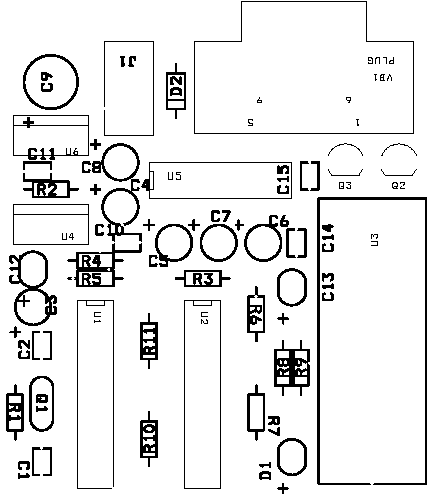
The pcb layout was made with orcad Layout Plus. The gerber file is available at download section below. Here I like to show how nice it is. The top and bottom layers are shown in Figure 2 and Figure 3. Figure 4 shows the component placement layout.
Figure 2: Top layer pcb x2 size.
Figure 3: Bottom layer pcb x2 size.
Figure 4: Component placment layout.
Bill Of Materials
The component list is shown in Figure 5. U1 the master chip must be programmed with writer1.hex before the programmer board can run properly. Q2 and Q3 are TO92 plastic package! With a CAN package, pin positions may differ on the layout. You can use any small signal transistors to replace them. VB1 is male type! All resistors can be 1/4W or 1/8W 5%.
Bill Of Materials January 4,2004 10:44:35 Page1 |
Figure 5: Component list.
Software
sdcc has the header file that declares bit variables and we can use them in program directly. We can define the specified bits as below,
#define LM317 P3_5 #define LE P3_7 #define prog P3_2 #define rdy P3_3 #define xtal P3_4 #define p10 P1_0 #define p11 P1_1 #define p12 P1_2 #define p13 P1_3 #define p14 P1_4 |
In c program, we can use assignment statement to set or clear them directly. For instance, function that makes low to high transition at P3.2,
pulseProg()
{
prog = 0;
prog = 0;
prog = 0;
prog = 1;
}
The ASCII strings were defined with modifier, 'code', so the compiled code will place them in code memory space.char code title[] = '\n\r Easy-Downloader V1.3 for ATMEL 89C2051/4051 (sdcc version)';
char code prompt[] = '\n\r >';
char code ok[] = '\n\r ok';
I have built function that print string to terminal, to make it compatible with the old version with Micro-C. Look at the source cod here,
putstr(char *s)
{
char i=0;
char c;
while((c=*(s+(i++)))!= 0) putchar(c); // while byte is not terminator, keep sending
}
The pointer s points to the start address of string. It will send character to serial port with function putchar while the character is not the terminator byte!Sdcc has no putchar( ) function, so we must build it before we can use. I wrote a simple putchar( ) as my assembly code.
void putchar(char c)
{
while(!TI);
TI=0;
SBUF = c;
}
We test TI bit before we can write a byte to SBUF. While TI is not set (buffer is not free) keep polling it, when it set, clear it and write a byte to SUF.The same as putchar( ) function, I had built the getchar( ) for this board to make it compatible with old version.
char getchar(void)
{
char c;
while(!RI);
RI =0;
c = SBUF;
putchar(c); // echo to terminal
return SBUF;
}
Now the code polls the RI bit, when it set, clear it and read SBUF and simply echo the received character with putchar( ) function.The important function is getnum ( ) function. Let me explain how it works?
unsigned int getnum()
{
char s[6];
char c;
char i;
unsigned int temp16;
c = 0;
i=0;
for (i = 0; c != 0xa; i++) // loop until CR has entered
{
putchar(xon); // send xon to signal host to send byte
c = getchar(); // get character from serial port
if(c == 0xd) c=0xa; // convert CR to LF to make it compatible with ez31 and ez41
s[i] = c; // save character to array
}
s[i-1] = 0; // put terminator at the end of string// convert ascii to integer (atoi(s))
temp16 = 0;
for(i=0; s[i] != 0; i++) temp16 = 10*temp16 + s[i]-'0';
return temp16; // return 16-bit for number of byte counting
}
Look at the red one, it is a simple for loop with condition to check the received character is NEWLINE or not. If not it will save the character being received to array s[i]. The putchar(xon) sends the xon to host to let it know the board is ready to receive a byte. The getchar( ) is not echo the received byte. However it converts CF to LF. When the loop found LF or 0xa, it will exit from the for loop and save terminator byte to s[i-1].The ascii string that saved in array s[] will be converted to 16-bit number with atoi code.
Most of the high level code are the same as previous version with Micro-C. You may study them in the source code then.
Let me shows you how to use sdcc to compile the source code again. The sample below uses batch file, s.bat.
C:\sdcc\app>s C:\sdcc\app>path=c:\sdcc\bin
C:\sdcc\app>sdcc writer1.c
library file /sdcc/share/sdcc/lib/small/libsdcc.lib
library file /sdcc/share/sdcc/lib/small/libint.lib
library file /sdcc/share/sdcc/lib/small/liblong.lib
library file /sdcc/share/sdcc/lib/small/libfloat.lib
C:\sdcc\app>packihx writer1.ihx>writer1.hex
packihx: read 166 lines, wrote 75: OK.
C:\sdcc\app>
The batch file s.bat contains,path=c:\sdcc\bin
sdcc writer1.c
packihx writer1.ihx>writer1.hex
The output machine code is hex file with *.ihx extension. We can use a tool, packihx to convert such hex file with *.ihx to *.hex easily.
The ez4.1 is suitable for programming the hex file into a 20-pin microcontrollers, 89C2051/4051. Since the hex file produced by sdcc is not sorted from low address to high address. The old version, EZ31 has bug for such hex file. So I recommened to use EZ4.1 for program loading.
- schematic:
- Layout in pdf:
- c compiler for 8051:
- firmware:
- HEX file:
- EZDL4:
- orcad files (schematic, layout):
- gerber file:
Errata
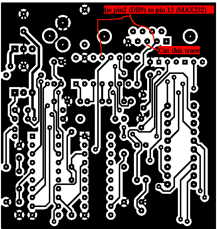
- 18 March 2004: found hardware schematic error at MAX232. The error is that pin 2 on the D-SUB 9 connector must be connected to pin 13 on the MAX232, not pin 8. The error had reported by Henrik Olesen, student at the University of Southern Denmark.
Below picture shows how to modify the pcb!


